JetBrains Platform
Plugin and extension development for JetBrains products.
From Java to Wayland: A Pixel’s Journey
What happens when we try to draw a single pixel in Java? The rendering triggers a sophisticated and multi-layered process. It begins within the high-level frameworks of Java’s Abstract Window Toolkit (AWT) or Swing, then flows through the Java 2D graphics pipeline, necessitating precise handling of color models, gamma correction, and coordinate-space transformations. To reach the Wayland compositor, the pixel is embedded within memory buffers shared between processes, subjected to thorough tracking of changed regions, and eventually presented on the display, completing its journey from an abstract computation to a tangible visual element.
This deep dive is intended for anyone working on Java UI optimization on Linux. It walks through the components and processes involved in carrying that pixel from your Java code to the display.
The beginning
We usually render in Java by making a draw call in an overridden
public void paint(Graphics g)
method of some AWT/Swing Component like so:
g.drawRect(x, y, 1, 1)
The Graphics object passed to every paint() provides a host of methods for drawing a given graphics primitive – like a tiny rectangle in our case – on the underlying canvas. Graphics redirects the actual work to an appropriate group of rendering algorithms collectively called a “graphics pipeline”.
The pipeline is chosen based on various properties of Graphics, such as rendering hints or the effective compositing algorithm (in other words, a method of overlaying semi-transparent colors). Should any of those properties change (for example, with a call like setRenderingHint(RenderingHints.KEY_ANTIALIASING, RenderingHints.VALUE_ANTIALIAS_ON)), Graphics will be forced to reconsider the decision about the pipelines and choose new ones to suit the new circumstances. The code responsible for this decision can be found in SurfaceData.validatePipe().
Rendering and raster
The input to a renderer is a mathematical abstraction of a two-dimensional shape and associated attributes (like color and stroke), and its output is a group of pixels representing that shape. The renderer uses a two-dimensional grid of pixels – a raster (specifically WritableRaster) – provided by the Graphics object as a canvas to paint on.
Note: Some renderers break large primitives into chunks (for instance, 32×32 units) and work with each chunk individually (for example, MarlinTileGenerator), which is why we can see – with certain tracing tools – a large amount of small window updates resulting from a single drawing operation.
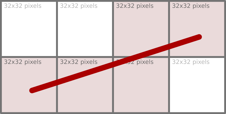
Moving pixels around in such small chunks is far from optimal from a memory-access point of view. We will return to how this problem is addressed later.
When painting on the window’s surface, we didn’t need to create any rasters to store pixels. Where did the raster come from then? Since we are painting on a window, that window must be the source of raster pixels – and this is true, up to a point.
Every AWT window that needs to be displayed on the screen has a counterpart in the native desktop windowing system. That counterpart is represented by a peer object (WindowPeer), which acts as a bridge between the native and Java parts of AWT. One of the bridge’s properties is the window’s content, represented as a SurfaceData object that stores the raster and handles all the low-level details. The peer manages this SurfaceData object and grants access to it upon request. Whenever a part of a window needs to be repainted, the AWT subsystem (sun.awt.RepaintArea) responsible for doing that obtains SurfaceData for the window wrapped in a Graphics object, which is later used as the target of various draw, fill, or clear operations.
Representing native windowing systems suggests that SurfaceData has to do more with the platform’s native code. At this level, SurfaceData is defined by a rather small API (see SurfaceData.h), with which we can lock a region of the surface (for reading, writing, or both), obtain a direct pointer to the raster, and then release it. This compact contract is enough to introduce a new surface type: Any platform or graphics subsystem can provide its own implementation of these functions, thereby plugging seamlessly into the Java 2D rendering pipeline without requiring modifications to the higher-level Java code.
Concrete implementations of SurfaceData exist for each supported rendering target. For in-memory images represented by BufferedImage, BufImgSurfaceData manages pixel data stored in the Java heap. For on‑screen rendering, platform‑specific variants handle the native windowing system: WLSMSurfaceData for Wayland, D3DSurfaceDatafor Direct3D on Windows, and MetalSurfaceData for macOS’s Metal framework, etc. Each of these subclasses supplies the necessary native hooks to lock the appropriate framebuffer or texture, ensuring that the same Java‑level drawing operations (whether performed by the Marlin renderer or by a hardware‑accelerated pipeline) can target any surface while keeping platform specifics isolated behind the stable SurfaceData interface.
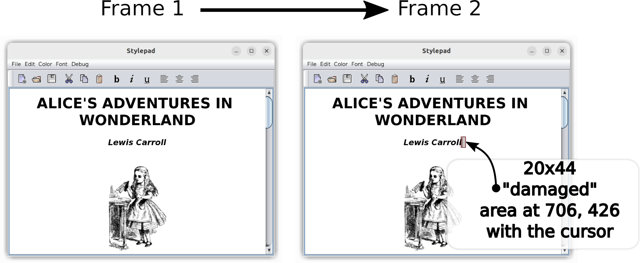
The locking mechanism in the Wayland compositor is crucial for efficient change tracking. Acting as a synchronization point, this locking function identifies precisely which areas of the surface are affected by a client’s buffer update, limiting further processing only to the “damaged” areas of the window.
We have established that, when painting on a window, the raster comes from the native window subsystem. With Swing, the situation with raster origins is more involved. Painting in Swing is routed through a class called RepaintManager, which accumulates changes made to the window’s surface and can be configured to use its own buffering strategy (for example, with the -Dswing.bufferPerWindow=true VM option). When such double-buffering is in effect, the repaint manager itself provides the canvas for the Swing components to paint on. Only after all updates (JComponent.paintToOffscreen()) are finished does it transfer the resulting image to the native window’s SurfaceData using an operation called blitting.
In the simplest case, blitting is just a memory copy operation. That, of course, can work only when both source and destination image formats are identical. If they are not, the very sophisticated Java 2D subsystem provides the blit algorithm that performs the conversion on the fly (see GeneralMaskBlit), but the performance of this operation suffers greatly compared to a simple memory copy. This is why, when working with BufferedImage objects, it is important to pick image formats that exactly match the native graphics system (i.e. SurfaceType of SurfaceData) and avoid conversions altogether. For this purpose, we have GraphicsConfiguration.createCompatibleImage().
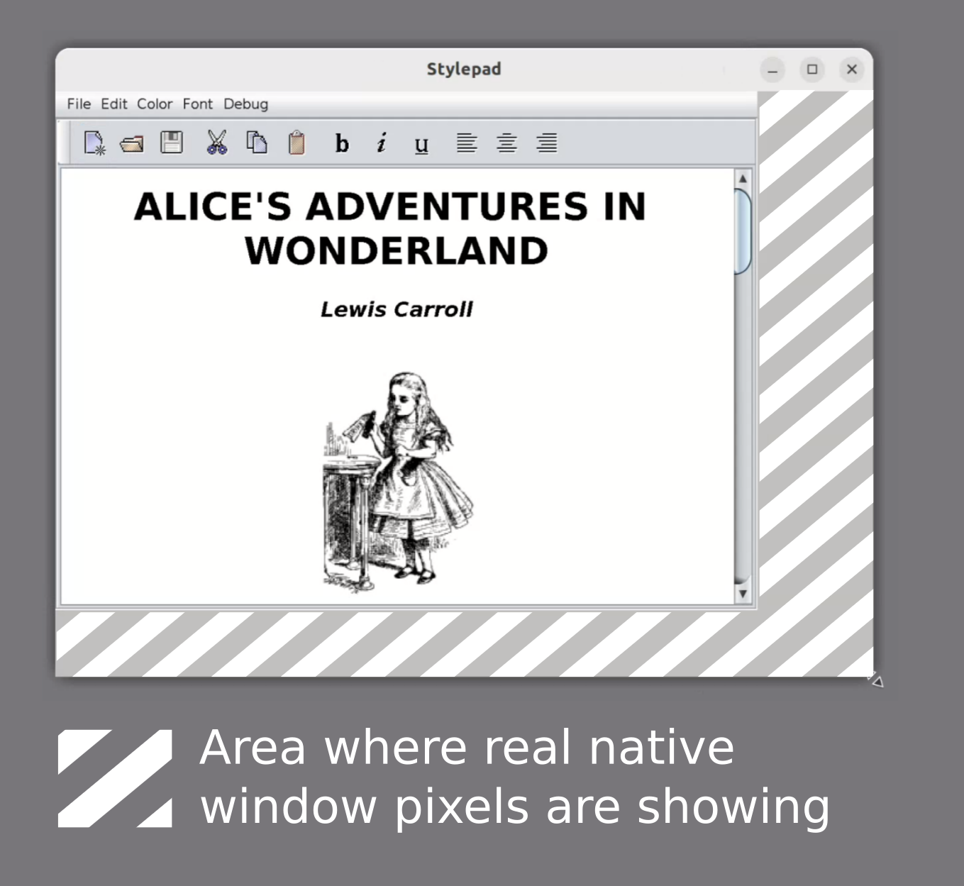
There’s one interesting side effect to the Swing double-buffering. The buffers that act as temporary storage for the future window content need to be resized whenever the window changes size. This resizing does not happen immediately, so when you enlarge a double-buffered Swing window very quickly, the buffer size may lag behind the new window size. This discrepancy makes the raw window SurfaceData raster visible at the resize edges for a moment.
Colors and blending
Each pixel in a raster consists of one or more data elements that correspond to color components like red, green, blue, and alpha. The ColorModel class defines how these data elements should be interpreted, serving as the bridge that converts an abstract color specification (such as an RGB or RGBA value) into the actual numerical values stored in a pixel. While this transformation may appear straightforward, it is in fact considerably more complex beneath the surface.
Take the alpha value, for example. Consider the color Color(255, 255, 255, 128), a semi-transparent white. Given a very straightforward conversion into a 32-bit RGBA pixel, which of the following is right?
0xFFFFFF800x808080800x80808000
The last one has lost the transparency value, which may seem like a bad thing at first, but it all depends on the context. If this pixel is not meant for further blending with other semi-transparent ones and will only be copied as is, it is as good as option (2). But do (1) and (2) represent the same pixel, though, especially given that their numeric values are different?
That’s where ColorModel.isAlphaPremultiplied() comes in.
When two images are overlaid (which happens a lot – think of a Button painted over a Frame background), the resulting value of each pixel is calculated according to the effective AlphaComposite rule. The compositing rule implements one of the Porter/Duff operations, with the default being AlphaComposite.SrcOverNoEa. In this most common case of painting a semi-transparent pixel over an opaque background, the resulting color component can be expressed as
result_color = destination_color * (1 - source_alpha) + source_color * source_alpha,
where source_alpha is normalized to the [0, 1] range (i.e. 0x80 is exactly a coefficient of 0.5).
There are two multiplications here: source_color * source_alpha applies the alpha value to the source pixel, and it needs to be done every time that pixel is used in a blending operation. This is, of course, somewhat expensive, given the size of images that need to be displayed on a typical 4K monitor (8,294,400 pixels). So it is common to store pixels with their alpha value already pre-multiplied. In this encoding scheme, a semi-transparent white is 0x80808080 rather than 0xFFFFFF80. Note how drastically the pixel value of the same color differs depending on ColorModel.isAlphaPremultiplied(). It is important to keep track of this property and apply it correctly.
Color space
So far, the color has been represented as a vector in three-dimensional space. One important implied characteristic of that space is that it is linear in emitted energy: A vector of (128, 128, 128) in a linear space emits twice as much energy as (64, 64, 64), for example. But that is not how human vision perceives the emitted light.
We can differentiate a greater number of dark colors, while the differences in very bright ones are less noticeable to the human eye. This suggests that, when encoding a color, more resolution is needed for dark tones, possibly at the expense of the bright side of the spectrum for perceptually linear results. The process of transforming a color according to this logic is called gamma encoding and can be approximately expressed as:
stored_value = linear_value ^ (1 / 2.2),
where 2.2 is the gamma value tuned to the sensitivity of human vision. This transformation function effectively allocates more code values for darker colors while compressing the intensity of bright colors.
Most consumer-level devices like displays expect their input pixel values to be in a non-linear color space called sRGB. The sRGB color space gamma uses a piecewise encoding function that remains linear near 0 values while maintaining an effective gamma of about 2.4, making it even more complex.
Since pixel values consumed by the hardware need to be in sRGB, we must store them in the same sRGB color space in Java to save on conversion. This is a widely used optimization, but it’s not without its pitfalls.
Gamma correction
Suppose we have just painted an image with non-opaque parts and we want to overlay it on top of some background. All images involved are in the sRGB color space to save on final conversion, as we have just noted. The blending function introduced earlier – for a source pixel with 0.5 alpha and the color black on a white background – simplifies to
result_color = (destination_color + source_color) * 0.5 = (255 + 0) * 0.5 = 127
But wait: We are applying the rules for blending in a linear space to a very non-linear one! The correct approach would be to first convert all the colors to the linear space, perform the blending operation, and convert the result back to sRGB. Following these steps, we get 188 instead of 127.
In terms of energy emission, 188 in the sRGB space corresponds to ~50% linear light intensity, while 127 emits only ~21%. So blending directly in sRGB without intermediate conversions results not only in an incorrect color, but also in darker visuals overall.
Performing those intermediate conversions, however, is very costly if we must do this for every displayed frame, especially in CPU-based pipelines. Consequently, it is common to blend images as if they were already in a linear space, applying some adjustments to compensate for the darker results. These kinds of conversion errors can actually live unnoticed for years because they affect all color components equally, making the incorrect result less obvious in many cases.
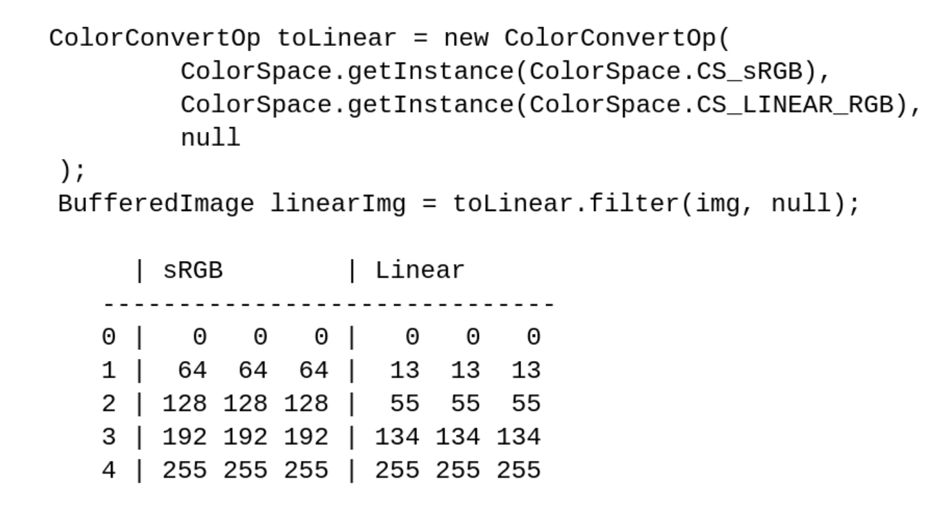
Note: To see the effects of color spaces on pixel values, use ColorConvertOp and access the image’s pixels directly through BufferedImage.getRaster().
Here are a few samples of gray pixels in sRGB space converted to a linear space with
Properties of Graphics
We have spent a great deal of time discussing the issues of colors and blending, but where did the actual color come from? It was not specified to the drawing primitive (the drawRect() call).
Color is actually one of many properties of a Graphics object. In practice, we typically encounter a Graphics2D object, which is in fact a descendant of Graphics. Color may be specified either implicitly at its creation or changed explicitly through, for example, Graphics.setColor().
In the simplest case, the painting color is SystemColor.windowText and the clearing (background) color SystemColor.window, which are obviously toolkit-dependent (initialized by Toolkit.loadSystemColors()). So when you paint with a Graphics object, you paint with Graphics.getColor(), and when you clear using, say, Graphics2D.clearRect(), you paint with Graphics2D.getBackground().
Coordinate systems
Going back to the starting point – g.drawRect(x, y, 1, 1) – are those 1 values really pixels? Which measurement units are those, or, more formally, what is the coordinate space the drawing primitives operate in? At this level, there are two spaces, with more to be added at the lower levels closer to the windowing subsystem (in our case, Wayland).
Java 2D abstracts away the real device coordinate space. All coordinates passed by the client application to Graphics are considered to be in the so-called ”user space”, which must be transformed at some point to the target device’s coordinate space, called the “device space”. The transformation function is yet another Graphics2D property with a default value, but it can be overridden as easily as the painting color with Graphics2D.setTransform().
Note: We don’t need to modify the program to experiment with this transformation function. By setting the sun.java2d.uiScale system property to anything other than the current monitor scale (say, 200%), we can make an existing application’s UI look larger (-Dsun.java2d.uiScale=3) or smaller (-Dsun.java2d.uiScale=1.4).
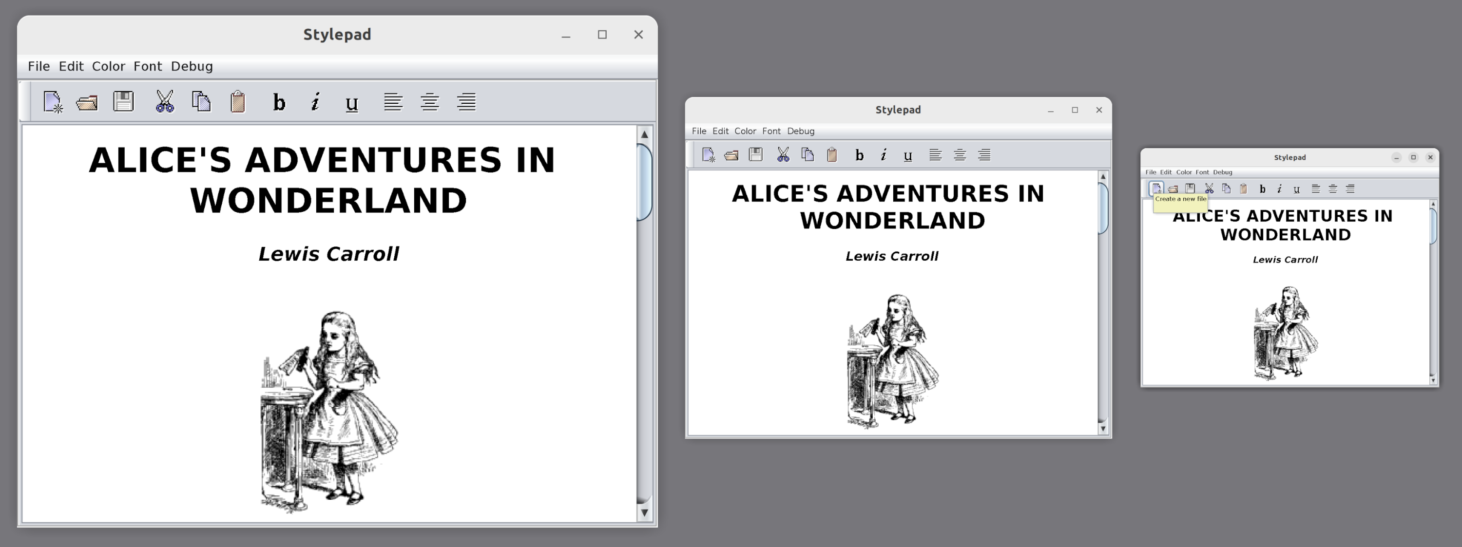
Thus, g.drawRect(x, y, 1, 1) will paint exactly one pixel only when the device’s scaling factor is 100% and is not overridden by anything in our program or by external factors. Even that guarantee holds only up to a point: The platform’s windowing subsystem may apply further transformations to the resulting image received from our Java program, either enlarging the image for a high-resolution display (likely resulting in blurry visuals) or shrinking it (for example, when an overview of all windows on a desktop is displayed when switching between them).
Wayland intro
Wayland provides several means of delivering window content from the client to the server and, eventually, to the screen. Here, we will concentrate on the most basic one that every Wayland implementation must support: shared memory buffers. But first, let’s look at an overview of the objects and protocols involved.
A window in Wayland is represented by an abstract entity called wl_surface. It has no properties of its own, not even a size. Rather, it serves as a convergence point for most window-related objects. What gives wl_surface its shape and visual image is another entity called a wl_buffer, which is attached to wl_surface through an attach request. Once a buffer gets attached to the window (and committed), the window displays that buffer’s pixels as a static image that does not change.
Wayland coordinate spaces
Wayland supports several ways to scale windows: An integer scale can be assigned to the surface’s buffer through set_buffer_scale, but the preferred way is the much more flexible wp_viewporter, which supports arbitrary transformations, including fractional scaling. The scaling operation is a simple affine transformation mapping one coordinate space to another. Most requests sent to Wayland and events received from Wayland (like mouse pointer movement) operate in the so-called “surface-local coordinate space”. Buffers that contain pixels to display live in their own coordinate space, and wp_viewporter (or buffer scaling) provides mapping between those spaces.
Earlier, we noted that there are two coordinate spaces in Java 2D. The one known as user space in Java 2D roughly corresponds to the surface-local coordinate space (the mapping is 1:1 as long as the system property sun.java2d.uiScale was not used). The device space is precisely the buffer coordinate space.
Buffers
If a buffer cannot change once attached to the window, how can we implement a blinking cursor or scroll the text displayed in a window? The Wayland API provides a straightforward solution: attaching a different buffer that has a modified raster. Delivering the change will obviously involve a lot of memory copying, which can be rather slow. Moreover, it is often the case that only a small portion of the image has changed. So the API needs to accompany the pending buffer with a list of rectangular regions that differ from the previous one, thereby avoiding whole-window repaints and unnecessary memory copying. In Wayland terminology, the changed regions are called “damage”. Nevertheless, even though the damage may be quite limited, an entirely new buffer needs to be created and attached to wl_surface to deliver the change.
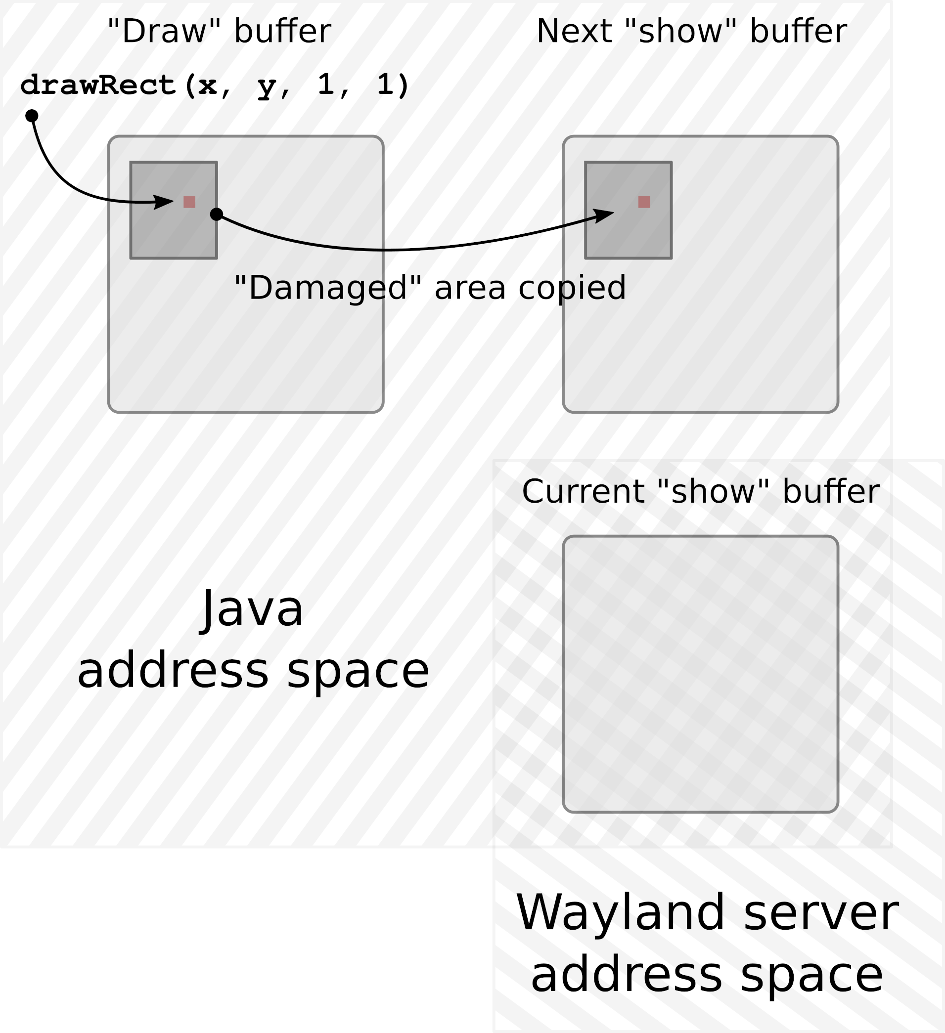
There are several wl_buffer implementations available today. JetBrains Runtime uses the POSIX shared memory object allocated through shm_open(3). This is basically a memory segment shared between the Java application and the Wayland server processes. A Java Swing or AWT application maps this segment into its address space and writes pixels to that segment, and the Wayland server subsequently maps the same segment to its own address space, reads the pixels, and displays them on the screen. The server then “returns” the buffer to the client, at which point the client is free to repaint it and resubmit it.
At first, it may seem that having just one such shared memory buffer would be enough. Sure, we will have to block the painting operations until the buffer is returned, but that may be acceptable, and in some cases, even preferred. After all, if we have to postpone the next frame because the server wasn’t ready to display a new one, we can already paint faster than the server can handle, so why waste CPU cycles trying to paint even faster?
However, this approach is not best suited to the Java model. In most cases, painting in Java is done on the same thread that handles all UI-related events. So if painting is blocked, keyboard input is blocked (including from typeahead), the mouse pointer is not tracked, and the entire application freezes and appears unresponsive. Furthermore, besides the more traditional model of reactive painting done by request of the system in a paint(Graphics) method, we can get a Graphics object from any Component and paint to that component on as many threads as we want, with no extra synchronization. Those threads would also block if we chose to have just one buffer and wait for it to be freed by the server.
To accommodate the model outlined above, a dedicated “drawing” buffer is created for each window, and this buffer is the target of all painting operations done on the window. Once the new frame has finished painting, that buffer is copied over to another buffer of exactly the same size, called the “show” buffer. This “show” buffer is then shared with the Wayland server.
This way, painting operations do not need to synchronize with the rate at which Wayland can deliver updates to the screen. The “drawing” buffer accumulates the new picture for as long as needed with no extra blocking. That does not mean we can bombard the server with new frames every millisecond. If, by the time the new frame is ready, the “show” buffer is still in use by the server, we must either wait for it to be returned or simply skip this frame, hoping the buffer will be returned the next time we try.
At this point, there are two buffers per window: one that we occasionally share with Wayland and another that we paint to. This is almost always enough. There are, however, Wayland implementations (Weston is one example) that will not return the buffer shared with the server unless and until another buffer is shared, replacing the previous one. Therefore, to accommodate such a scenario, we must have not two, but three buffers per window.
Note: Having more than three buffers might theoretically help if we could generate new frames very quickly and the server could receive them at the same speed but struggle to return the buffers just as fast. However, in practice, increasing the buffer count beyond three has not resulted in an improved frame rate, suggesting this is mostly a hypothetical scenario.
Damage grouping
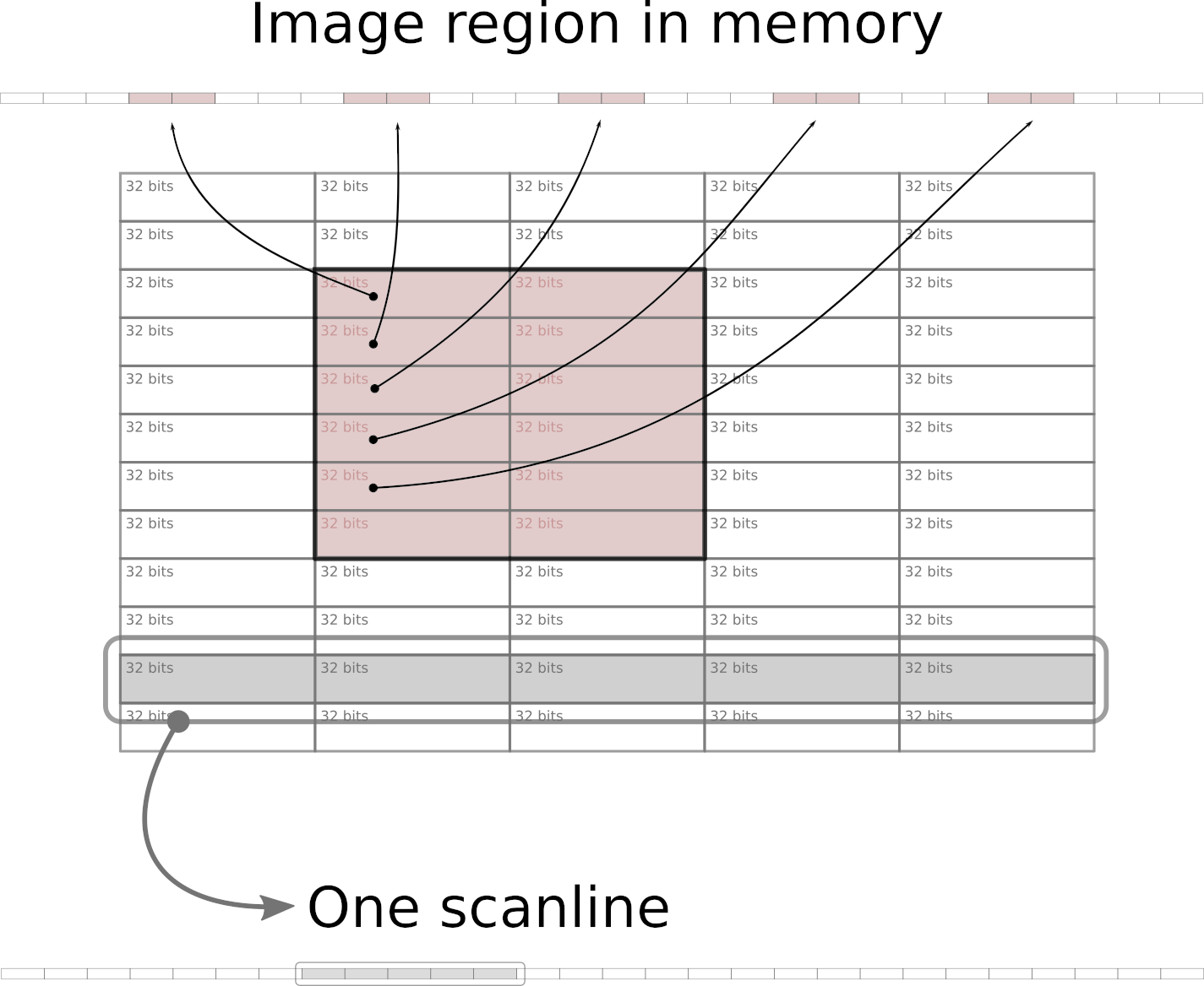
In memory buffers, images are stored as a sequential array of 32-bit integers starting from the topmost scanline (horizontal row of pixels), and proceeding from left to right. This means, among other things, that rectangular areas within an image that do not extend fully from left to right are not sequential in memory. Because of many caching techniques employed at various levels – from memory controllers and CPUs up to operating systems – copying a larger sequential chunk of memory can actually be done faster than copying several much smaller chunks that are located apart from each other in memory.
Earlier, we noticed that various renderers in the graphics pipeline, when painting a new frame to be delivered to the screen, may modify a large number of small adjacent regions. Additionally, when scrolling the file list in the IDE, a narrow vertical rectangle gets damaged, modifying a small portion of almost every scanline in the IDE window with changes located far apart in memory.
The damage grouping algorithm evaluates incoming changes and merges affected rectangles, sometimes deciding in favor of a much larger rectangle that consists of full scanlines. Copying such areas can reduce the overall time required for transferring image updates by a few milliseconds.
The end
And so the newly painted pixel – likely together with many more surrounding pixels – was written into the drawing buffer of the window. Once the painting was completed for the entire window, the updated regions were copied over to one of the available show buffers, and that buffer was then shared with the Wayland server. The damage list included the area occupied by the painted pixel, making sure the server knows what new information to show. The pixel is now halfway through its journey.
It started its life as a data structure describing its visual characteristics (location, size, color, transparency, color space, etc.), was transformed into a sequence of bytes, and then moved around quite a bit. Now it leaves the familiar address space of a Java process to be welcomed by the Wayland server, which will guide it through the desktop compositing to the graphics driver, and finally to the screen.
References
- Alpha compositing
- Porter/Duff Compositing and Blend Modes
- What every coder should know about gamma
- Wayland protocol
- Wayland Book
- What Every Programmer Should Know About Memory