.NET Tools
Essential productivity kit for .NET and game developers
Create UML Diagrams using PlantUML

UML, or Unified Modeling Language, is, as the name implies, a modeling language that allows you to visualize systems. In this post, we’ll look at how PlantUML enables you to create various kinds of diagrams so that you can properly document your software. We’ll create two of the most popular UML diagram types: Class and Use Case diagrams, to demonstrate what you can do with the PlantUML plugin in Rider.
UML Overview
UML is a language. But it isn’t a programming language in the sense C#, Java, or Python are. UML is a visual way to convey information about software or systems, through diagrams. PlantUML is a UML-based component that enables you to draw diagrams using a concise syntax. UML diagrams come in many flavors, including the following popular types of diagrams:
- Class: Diagrams all of the classes in a program, and how they are related.
- Component: Shows the various components of a system and how they interact.
- Use case: Visually demonstrates varying scenarios in how users and other software interacts within a system boundary.
- Activity: Graphic representation of workflows of a system.
- Sequence: Outlines the steps that are necessary for a system or part of a system to function.
- State-machine: Describe the behavior of objects that act differently according to the state they are in at the moment.
In addition, PlantUML supports Object, Gantt, MindMap, Wireframe, and Work Breakdown Structure diagrams. Most teams don’t create every type of diagram for a system. Instead, they tend to choose which UML diagram types are the most meaningful that help the team and other stakeholders better understand the software. For example, a team that works on UIs might find Use Case diagrams helpful, while the back-end team might find Sequence and State-machine diagrams work better for their software.
Create UML diagrams with PlantUML
Use the PlantUML plugin in Rider to create UML diagrams that can be integrated into your codebase. Start by adding a .puml file. Each new file that PlantUML creates contains example PUML, which is PlantUML’s own syntax for creating UML diagrams. Because PUML syntax is clean, compact, and efficient, folks can use it not just for visual diagrams but also as a basis for code generation or documentation.
Notice the PUML syntax and the corresponding visualization in the PlantUML tool window to the right of the editor window. All PlantUML files begin with the @startuml marker and end with the @enduml marker. In between these markers is basic syntax that generates the diagrams, though diagrams can be as complex as is necessary
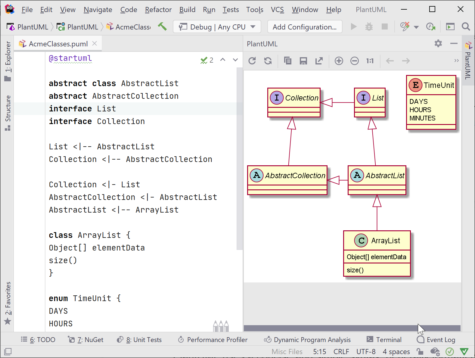
PlantUML’s terse syntax is generally formatted as a keyword identifier followed by the name of the subject. For properties, a colon goes between the property name and its type. For methods, use parentheses immediately after the method name. As you write these tokens, PlantUML automatically and immediately creates the UML diagrams, and updates the visual map that is shown in the PlantUML tool window.
A few PlantUML syntax basics:
interface interface-name
class class-name
abstract class class-name
property: data-type
method-name()
Colors and other visual indicators are customizable through PlantUML syntax.
Use the PlantUML toolwindow to manage diagrams, for example, refreshing or zooming into a diagram. You may want to save them as a separate file, perhaps to include in documentation. PlantUML supports .png, .svg, .utxt, .atxt, and .eps formats when saving.
Class diagrams
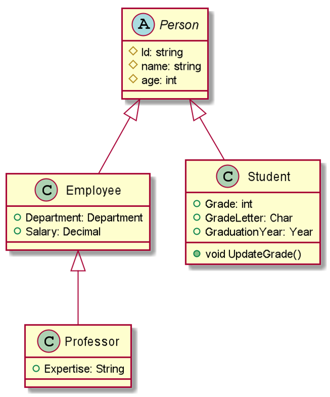
Class diagrams present the business objects from a system, along with an outline of their data and behaviors and how they relate to each other. Diagrams give developers a view as to the overall structure of a program. Class diagrams are used for many purposes, from generating data models in code to serving as documentation.
For example, if a class diagram is needed for a university, the following syntax can be used to create the following diagram. Notice the PlantUML syntax contains tokens for everything that UML requires, such as access modifiers (# for protected, + for public) and data types after a colon. To create an inherited model, use the Base <|-- Derived syntax. While this example shows only a few features of an object model, PlantUML supports other access modifiers and markers for composition and aggregation as well.
@startuml

abstract class Person {
    #Id: string
    #name: string
    #age: int
}

class Employee {
    +Department: Department
    +Salary: Decimal
}

class Professor {
    +Expertise: String
}

class Student {
    +Grade: int
    +GradeLetter: Char
    +GraduationYear: Year
    +void UpdateGrade()
}

Person <|-- Employee
Employee <|-- Professor
Person <|-- Student

@enduml
Classes in PlantUML diagrams can represent classes in C#, Java, or any OO language. In this case, PlantUML’s syntax is almost the same as C#. Use the class keyword, curly braces, then list the members and types (but no code!). This familiarity should ease the burden of creating diagrams that match objects in your model.
Use cases
Use case diagrams demonstrate the interaction between users (actors) and software, and between software components. They are an excellent way to get a snapshot of which parts of a complex system must integrate together, and how components connect to each other, as well as some system flow.
Below is a sample of PlantUML use case syntax and an accompanying visual diagram:
@startuml

left to right direction
skinparam packageStyle rectangle

actor Professor
actor Student
actor Staff

rectangle University-System {
    Professor --> (Grade Exam)
    Professor --> (Manage Course)
    Professor ---> (Access Course Information)
    Student ---> (Access Course Information)
    Student ---> (Enroll in Course)
    Staff ---> (Access Course Information)
    Staff ---> (Manage Course)
}

@enduml
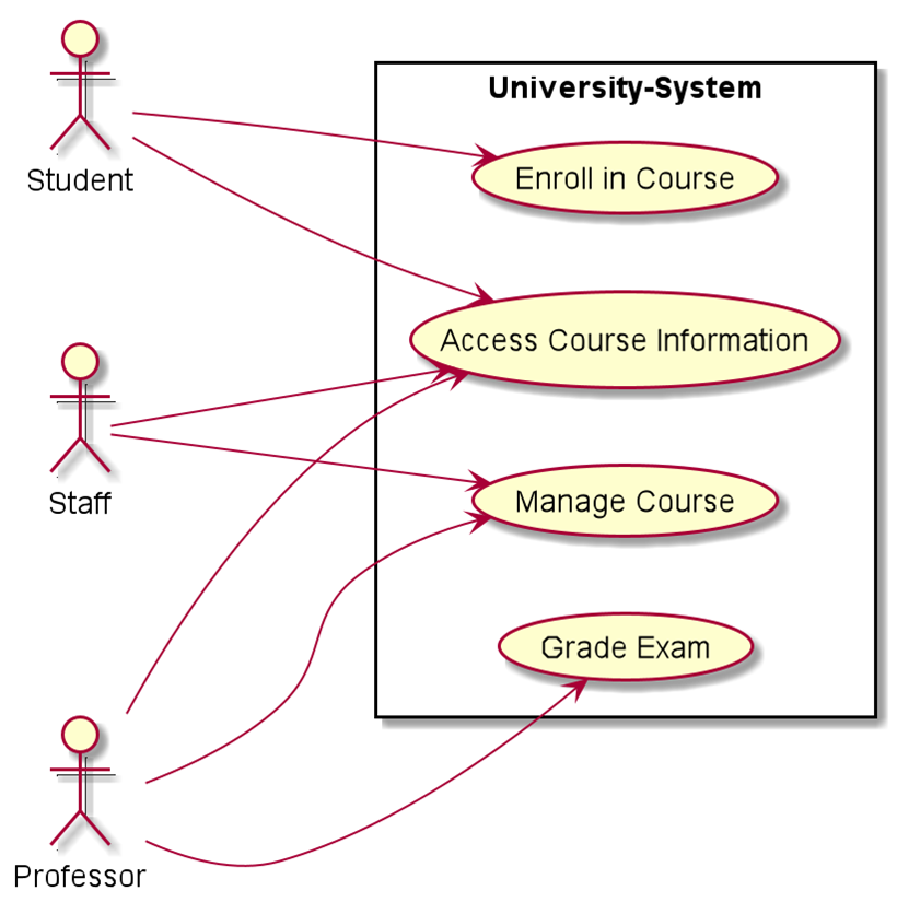
Notice some of the syntax: rectangle is used to define the system boundary. Actors are defined by the actor keyword, and the relationship between actors and objects (or objects to objects) are defined with --->. The use cases themselves are enclosed in parentheses. PlantUML really does have precise syntax, which can help you create diagrams faster with better efficiency.
Summary
Most companies, especially large organizations with complex software, need to model, map, and manage their software with industry-standard UML diagrams. PlantUML supports the most popular kinds of UML diagrams and should suit most needs.
If you’re using Rider, diagramming your systems is built into the product as a plugin, giving you an advantage to complete projects faster and more efficiently. So download Rider today, and show us your diagrams!